S32K5 MCAL 驱动 API 与休眠设计方案映射分析
S32K5 MCAL 驱动 API 与休眠设计方案映射分析
分析对象:S32K5_R52_M7_休眠方案_CN.md / S32K5_R52_M7_Sleep_Design_EN.md(已修订版)
分析基准(取自 IMA 知识库「米多papa的知识库 / MCAL」文件夹)
| 文档 | 编号 | 说明 |
|---|---|---|
| User Manual for S32K5 MCU Driver | UM85MCUASRR23-11 Rev. 1.0 | NXP 实现的 S32K5 MCU 驱动用户手册(231 页) |
| Integration Manual for S32K5 MCU Driver | IM85MCUASRR23-11 Rev. 1.0 | 集成手册(编译器/链接器选项、必需文件) |
| Specification of MCU Driver | AUTOSAR CP R23-11 (SWS_MCUDriver) | AUTOSAR 官方规范,54 页 |
| Requirements on MCU Driver | AUTOSAR CP R23-11 (SRS_MCUDriver) | AUTOSAR 官方需求,17 页 |
✅ 关键确认:该 MCU 驱动 User Manual 的「Supported Derivatives」明确列出 s32k566_lfbga324 / s32k566_lfbga437,即与本文档的 S32K566 目标完全一致。这套 API 就是为你的芯片提供的。
一、核心结论
设计文档描述的是底层寄存器级流程,而 MCAL MCU 驱动已经把这套流程封装成了标准 AUTOSAR 服务。二者关系是:文档流程 ≈ MCU 驱动内部实现,绝大多数步骤不需要应用层手写。
但有 3 个关键缺口:设计文档完全没提 MCAL 驱动的存在,导致集成时会出现职责空白。详见第四节。
二、S32K5 MCU 驱动覆盖的 API 清单
AUTOSAR SWS R23-11 定义的 MCU 驱动服务共 11 个,S32K5 MCU 驱动实现情况如下(Service ID 以 SWS R23-11 原文为准):
| 服务名 | Service ID | 同步/异步 | 可重入 | 与休眠方案的关系 |
|---|---|---|---|---|
Mcu_Init |
0x01 | 同步 | 可重入 | 前置:所有其他 API 前必须先调用 |
Mcu_InitRamSection |
0x02 | 同步 | 可重入 | PD0 SRAM 段初始化 |
Mcu_InitClock |
0x03 | 同步 | 可重入 | ⭐ SW3/SW4 都要用:切系统时钟到 FIRC、关 PLL |
Mcu_DistributePllClock |
0x04 | 同步 | 可重入 | 唤醒后重新分发 PLL 时钟(S32K5 有偏差,见下) |
Mcu_GetPllStatus |
0x05 | 同步 | 可重入 | 查询 PLL 锁定状态 |
Mcu_GetResetReason |
0x06 | 同步 | 可重入 | ⭐ 唤醒后判断为何被唤醒 |
Mcu_GetResetRawValue |
0x07 | 同步 | 可重入 | 读取原始复位寄存器值 |
Mcu_SetMode |
0x08 | 同步 | 可重入 | ⭐⭐ 本方案的核心 API |
Mcu_GetVersionInfo |
0x09 | 同步 | 可重入 | 版本查询 |
Mcu_PerformReset |
0x0a | 同步 | 可重入 | 触发软件复位(受 McuPerformResetApi 编译开关控制,见 SWS_Mcu_00146) |
Mcu_GetRamState |
0x0b | 同步 | 可重入 | 查询 RAM 内容状态(S32K5 标注为 BSW13701 可选) |
⚠️ Service ID 注意事项:
Mcu_PerformReset在 SWS 中是条件服务(SWS_Mcu_00146:仅当McuPerformResetApi为 TRUE 时提供),因此其编号在不同 AUTOSAR 版本间存在偏移。本表按 R23-11 原文排列,实际取值请以你所用 MCAL 版本的Mcu_Cfg.h/Mcu.h为准。
与休眠方案直接相关的三个 API
1. Mcu_SetMode — 核心 API
void Mcu_SetMode (Mcu_ModeType McuMode);
SWS 定义的关键约束(SWS_Mcu_00147):
The function Mcu_SetMode shall set the MCU power mode. In case of CPU power down mode, the function Mcu_SetMode returns after it has performed a wake-up.
SWS_Mcu_00148:
The MCU module’s environment shall only call the function Mcu_SetMode after the MCU module has been initialized by the function Mcu_Init.
两条重要 Note(SWS 原文):
Note: The environment of the function Mcu_SetMode has to ensure that the ECU is ready for reduced power mode activation.
Note: The API Mcu_SetMode assumes that all interrupts are disabled prior the call of the API by the calling instance. The implementation has to take care that no wakeup interrupt event is lost. This could be achieved by a check whether pending wakeup interrupts already have occurred even if Mcu_SetMode has not set the controller to power down mode yet.
2. Mcu_InitClock — 时钟切换
负责 SW3/SW4 的时钟动作:把系统时钟切到 FIRC、关闭 PLL。S32K5 MCU 驱动 User Manual 明确:
Before entering the software Standby mode sequence, the system clock source must be changed to FIRC because PLLDIG is not available in Standby mode. In this mode, all clock sources can be optionally disabled (including FIRC, which results in a no-clock, low-power consumption mode). You could use FXOSC, if enabled, when the 2.5 V supply is available by appropriate configuration of PMC’s CONFIG[LPM25EN].
3. Mcu_GetResetReason — 唤醒源判定
唤醒后判断是哪个复位源导致唤醒(对应你文档中「唤醒原因」共享区)。
三、驱动内部实现:SW1–SW4 四阶段
这是本次分析最关键的发现。S32K5 MCU 驱动 User Manual §3.6.6 明确给出了进入低功耗模式的完整软件阶段划分,与设计文档的步骤高度对应:
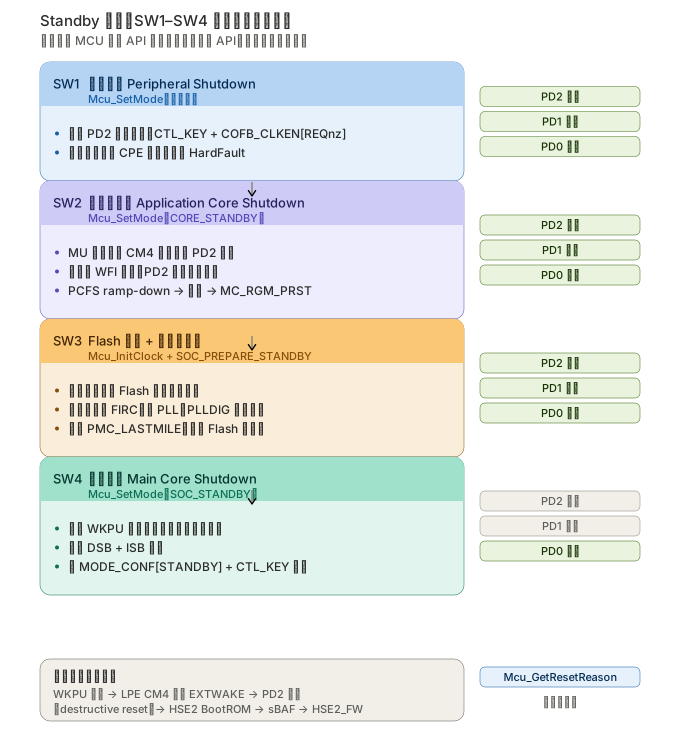
| 阶段 | 名称 | 驱动 API 调用 | 对应设计文档步骤 |
|---|---|---|---|
| SW1 | Peripheral Shutdown | Mcu_SetMode(外设关断集) |
第 4 节 Step 4.1-4.3 关停 PD2 外设 |
| SW2 | Application Core Shutdown | 应用核调 Mcu_SetMode(CORE_STANDBY);主核调 Mcu_SetMode(McuCoreUnderMcuControl 勾选 + McuCoreClockEnable 取消勾选) |
第 4 节 Step 2-3 WFI 协调与关钟 |
| SW3 | Flash Low-Power Handshake + PMC_LASTMILE Regulator Disable | Mcu_InitClock(切 FIRC、关 PLL);Mcu_SetMode(SOC_PREPARE_STANDBY) |
设计文档未覆盖(见缺口 1) |
| SW4 | Main Core Shutdown | 配置唤醒 IP;Mcu_SetMode(SOC_STANDBY),McuMainCoreSelect 设为执行该转换的核 |
第 4 节 Step 4.7-4.10 请求模式切换 |
SW2 的两步握手(与你的设计文档高度一致)
User Manual 原文:
- From the main core, request the application core(s) to stop.
- Transition the application core(s) into standby (i.e. the application core(s) must call
Mcu_SetModewith a mode configuration having “McuPowerMode” = CORE_STANDBY)- From the main core, shutdown the application core(s) (i.e. the main core must call
Mcu_SetModewith a mode configuration having the “McuCoreUnderMcuControl” checkbox(es) checked and “McuCoreClockEnable” checkbox(es) unchecked for the application core(s) to be shutdown)
这印证了你文档第 4 节「Requestor Core 协调其他核心 WFI 再关钟」的设计是符合驱动实现思路的。
关键配置参数(Tresos / MCAL 配置)
| 参数 | 作用 |
|---|---|
McuPowerMode = CORE_STANDBY |
应用核自身进入 Standby |
McuPowerMode = SOC_PREPARE_STANDBY |
SoC 预备阶段(SW3) |
McuPowerMode = SOC_STANDBY |
SoC 真正进入 Standby(SW4) |
McuCoreUnderMcuControl |
勾选表示该核/分区由 MCU 驱动接管(取消勾选则应用自己管) |
McuCoreClockEnable |
控制该核时钟开关 |
McuMainCoreSelect |
指定执行 Standby 转换的主核 |
User Manual 的重要配置建议(§3.6.2):
For bypassing the configuration of a Partition, COFB set, or Core during
Mcu_SetMode, the corresponding “[Block] Under MCU Control” checkbox should be unchecked. This will generate smaller configurations that NXP will be updated faster and more efficiently. In addition, if the application is configuring a certain mode in advance, the UnderMcuControl should be unchecked so the MCU driver does not overwrite the initial settings.Note: Clock for main Core must be always enabled by
McuCoreUnderMcuControlshould be unchecked if main core configured by application orMcuCoreUnderMcuControlandMcuCoreClockEnablemust be checked together.
⚠️ 这条对你的双核方案很关键:主核时钟必须保持使能。若主核由应用自己配置,需同时勾选
McuCoreUnderMcuControl与McuCoreClockEnable,否则关断时会出问题。
时钟模式选项(§3.6.7)
| 选项 | 模式 | CORE_CLK | 可用模式 |
|---|---|---|---|
| A | High Performance | 160 MHz | 仅 Run |
| B | Reduced Speed | 120 MHz | 仅 Run |
| C | Boot Standby | 24 MHz | Standby |
| D | Low-Speed RUN | 48 MHz | — |
| E | Low-Speed Run | 3 MHz | — |
| E2 | Very-Low-Speed Run | 750 kHz | — |
| F | 1:1 模式(CORE_CLK = AXBS_CLK) | — | 仅 Run |
四、设计文档的 3 个集成缺口
缺口 1:SW3 阶段完全缺失 ⭐ 最重要
设计文档现状:第 4 节 Step 4 的 10 步里,没有 Flash 低功耗握手,也没有 PMC_LASTMILE 稳压器关闭。
驱动要求(User Manual §3.6.6.3 原文):
The application will disable the PLL (and optionally disable FIRC/SIRC/SXOSC/FXOSC as per power consumption requirement in order to reduce power consumption in STANDBY mode) and ensure that no flash high voltage operations are ongoing.
- Suspend or wait for any ongoing flash high voltage operations.
- Configure FIRC as the system clock and disable the PLL (i.e. call
Mcu_InitClockwith such a clock configuration)- Prepare the SoC for standby mode (i.e. call
Mcu_SetModewith a mode configuration having “McuPowerMode” =SOC_PREPARE_STANDBY)
为什么这一步不可省:PMC_LASTMILE 是给 MRAM/Flash 供电的末级稳压器。Standby 下若不关,Flash 阵列仍耗电,低功耗目标直接落空。而「等待 Flash 高压操作结束」若省略,Flash 编程中途掉电会导致非确定性行为(User Manual §3.6.3 也强调过 flash 编程模型在操作中途被修改会导致 non-deterministic behavior)。
修订建议:在设计文档第 4 节 Step 4 插入 SW3 阶段:
SW3: Flash 低功耗握手与 PMC_LASTMILE 关闭
  a. 挂起或等待进行中的 Flash 高压操作结束
  b. 切换系统时钟到 FIRC,关闭 PLL(驱动 API:Mcu_InitClock)
  c. 配置 SoC 进入 Standby 预备态(驱动 API:Mcu_SetMode, McuPowerMode = SOC_PREPARE_STANDBY)
缺口 2:未说明 EcuM 的唤醒中断责任
User Manual §3.6.6 Note 原文:
The EcuM shall ensure that no wakeup interrupt event is lost. The MCU driver cannot handle wakeup interrupt as it doesn’t have any information related to those. It is responsibility of the application to ensure that no wakeup interrupt occurs before the SoC completes the standby mode transition.
SWS_Mcu_00147 的 Note 也要求:
The API Mcu_SetMode assumes that all interrupts are disabled prior the call of the API by the calling instance. The implementation has to take care that no wakeup interrupt event is lost. This could be achieved by a check whether pending wakeup interrupts already have occurred even if
Mcu_SetModehas not set the controller to power down mode yet.
设计文档现状:第 7 节总结表完全没提中断使能/屏蔽的责任划分,也没提 EcuM。
这是一个真实的功能风险:若在 Mcu_SetMode 调用前有唤醒中断 pending,可能丢事件。设计文档第 4 节虽然写了「Requestor Core 先 Disable IRQ」,但没有说明这是 AUTOSAR 的强制前提,也没有说明唤醒中断的检查责任在 EcuM。
修订建议:在第 7 节总结表增加一行:
| 中断责任 | 调用 Mcu_SetMode 前必须屏蔽所有中断;EcuM 负责确保无唤醒中断丢失(MCU 驱动无法感知) |
缺口 3:LPM25EN(2.5V 供电才能用 FXOSC)未提及
User Manual §3.6.6 原文:
You could use FXOSC, if enabled, when the 2.5 V supply is available by appropriate configuration of PMC’s CONFIG[LPM25EN].
设计文档现状:第 4 节 Step 4.4 只写「切换系统时钟到 FRO,关闭 PLL」,没提 FIRC / FXOSC 的选择条件,也没提 LPM25EN。
结合我上一轮的 RM 核对,这里有个值得注意的差异:
- RM Ch53 §53.3.2.2 说 LPRUN 下应用需切到「FXOSC, SXOSC, SIRC, FIRC」这些时钟
- MCU 驱动 UM 说 Standby 前必须切到 FIRC,因为 PLLDIG 不可用;并额外提到 LPM25EN 与 2.5V 供电
两者不冲突(FIRC 也在 RM 列出的可用时钟中),但驱动把「切 FIRC」定为 Standby 的强制动作,比你文档写的「切 FRO」更严格。FRO 属 PD0 常开时钟,而驱动选择 FIRC 是因为 FIRC 在 Standby 下仍活动且 HSE2 可配置它。
修订建议:Step 4.4 改为:
4. 切换系统时钟到 FIRC,关闭 PLL(LPRUN/Standby 下 PLLDIG 不可用)
   - Standby 入口必须切 FIRC(驱动要求)
   - 若 2.5V 供电可用且已配置 PMC.CONFIG[LPM25EN],可用 FXOSC
   - 所有时钟源均可选关闭(含 FIRC),全关即 no-clock 最低功耗模式
五、S32K5 驱动已知偏差与限制(影响方案实现)
5.1 与 AUTOSAR 规范的偏差(§3.4 Deviations)
| Requirement | 状态 | 说明 | 对方案的影响 |
|---|---|---|---|
SWS_Mcu_00053 |
N/S | 时钟失败通知 MCU_E_CLOCK_FAILURE 无法在 ISR 上下文上报,改用 MCU_E_ISR_CLOCK_FAILURE 由 CMU 中断上报 |
LPRUN 切换时钟时若发生时钟失败,走的不是标准错误码,需按 S32K5 变体处理 |
SWS_Mcu_00056 |
N/S | Mcu_DistributePllClock 在 PLL 已被硬件自动激活时仍会改动硬件,且切换到 PLL 的动作不由 Mcu_InitClock 完成 |
⚠️ 重要:唤醒后恢复 PLL 时钟需要显式调用 Mcu_DistributePllClock,不能指望 Mcu_InitClock 顺带完成 |
SWS_Mcu_00259 |
N/S | 不支持的分区分区映射配置拒绝检查(基于 ticket AAI-462,不适用) | — |
SWS_Mcu_CONSTR_00001 |
N/S | 「模块在各分区独立实例运行」不适用(基于 ticket AAI-462) | — |
SWS_Mcu_00056这一条对你的唤醒流程影响最大:设计文档第 5 节唤醒流程写「PD2 上电 → HSE2_FW 使能应用核 → 恢复上下文 → 回到 RUN」,但没有提时钟如何恢复。PLL 恢复需要单独调Mcu_DistributePllClock。
5.2 驱动限制(§3.5 Limitations)
| 限制 | 后果 | 与方案的关系 |
|---|---|---|
| Selecting PowerOffState for CPE_LLC0/CPE_LLC1 会导致 HardFault,因为驱动仍尝试读写无供电的分区 | 规避:选 PowerOnState | ⚠️ 若你的关断流程涉及 CPE_LLC(Cache),必须注意 |
| 同时禁用 PARTITION_CPE_0_INDEX 和 PARTITION_CPE_1_INDEX 会 HardFault:禁用 CPE_1 会关闭整个 CPE 系统,导致后续禁用 CPE_0 时 HardFault | 规避:一次只禁用一个 CPE 分区 | ⚠️ 直接约束 Step 4 的外设/分区关断顺序 |
| 核心启动地址的 linker symbol 是硬编码的 | 更换核需改链接脚本 | 涉及 M7/R52 分核启动 |
不支持 Design Studio 的示例工程;时钟树频率无法导出到 McuClockReferencePoint 表 |
需自定义参考点 | 配置阶段注意 |
| 多个时钟的频率上下限被设为 0–10 GHz(RM/DS 未提供明确信息) | 频率检查形同虚设 | 时钟配置需人工核对 |
5.2 的第二条是硬约束:
Disable only one CPE partition at a time (PARTITION_CPE_0_INDEX or PARTITION_CPE_1_INDEX)。你的设计文档第 4 节 Step 4.2 写「关停 PD2 外设时钟」时,若涉及 CPE 分区,必须按分区逐个关,不能批量关。
六、MCAL 分层职责划分建议
基于以上分析,设计文档应补充以下职责边界:
| 层 | 职责 | 具体内容 |
|---|---|---|
| 应用 / OS(两个 OS 各自) | 上下文保存、任务停止、唤醒源配置 | 保存上下文到 PD0 SRAM;停任务;配置 WKPU;置位「本核已就绪」标志;执行 WFI |
| 核间通信(MU 中断) | 休眠握手 | 通知 CM4 停止用 PD2 外设;Requestor Core 收集各核 WFI 状态 |
| EcuM | 唤醒中断不丢失 | ⭐ 保证进入 Standby 前无 pending 唤醒中断;模式转换期间不产生唤醒中断 |
| MCU 驱动(MCAL) | ⭐ 寄存器级全部流程 | SW1 外设关断 / SW2 核关断 / SW3 Flash 握手 + PMC_LASTMILE / SW4 主核关断;时钟切换;Mcu_GetResetReason |
| MCAL 配置(Tresos) | 静态配置 | McuPowerMode、McuCoreUnderMcuControl、McuCoreClockEnable、McuMainCoreSelect、McuDisableFlashWaitStatesConfig |
换言之:设计文档第 4 节 Step 3 / Step 4 的寄存器级步骤(PCFS ramp-down、CTL_KEY 密钥、COREn_PCONF[CCE]、COFB_CLKEN[REQnz]、MODE_CONF、DSB+ISB)全部由 MCU 驱动内部完成,应用层不应直接操作这些寄存器。
⚠️ 但要注意:文档第 4 节 Step 2 的 WFI 状态查询(MC_ME.PRTN0_CORE0_STAT[WFI] 等)驱动内部会做。如果应用层想自己轮询确认,需要评估是否与驱动冲突——推荐做法是让驱动做,应用层只用 MU 标志位握手。
七、建议修订清单(新增)
| 优先级 | 动作 | 依据 |
|---|---|---|
| P0-A | Step 4 插入 SW3 阶段(Flash 高压操作等待 → FIRC 切换关 PLL → SOC_PREPARE_STANDBY),含 PMC_LASTMILE 关闭 |
UM §3.6.6.3 |
| P0-B | Step 4.4 时钟切换改为切 FIRC(Standby 强制),补 LPM25EN 与 2.5V 条件 | UM §3.6.6 |
| P0-C | 补充「一次只关一个 CPE 分区」的硬约束(否则 HardFault) | UM §3.5 |
| P1-A | 总结表增加「EcuM 负责唤醒中断不丢失」,并注明 Mcu_SetMode 前必须屏蔽所有中断 |
UM §3.6.6 Note + SWS_Mcu_00147 |
| P1-B | 唤醒流程补充「PLL 恢复需显式调用 Mcu_DistributePllClock」 |
UM §3.4, SWS_Mcu_00056 |
| P1-C | 补 Mcu_GetResetReason 用于判定唤醒源 |
SWS 服务清单 |
| P1-D | 补 CPE_LLC0/1 选 PowerOffState 会 HardFault 的告警 |
UM §3.5 |
| P1-E | 补主核时钟必须保持使能的配置约束 | UM §3.6.2 Note |
| P2-A | 说明「设计文档寄存器步骤由驱动内部完成,应用层不应直接操作」 | 综合 |
| P2-B | 建议用 MU 标志位握手替代应用层直接读 WFI 寄存器,避免与驱动冲突 | 综合 |
| P2-C | 时钟失败错误码变体说明(MCU_E_ISR_CLOCK_FAILURE) |
UM §3.4 |
八、与上一轮评审的关系
上一轮 RM 评审的修订依然全部有效——那些是寄存器级的正确性,MCAL 驱动内部正是这么做的。
本轮补充的是集成层:
- RM 告诉你「应该怎么做」→ 已修订进文档
- MCU 驱动 UM 告诉你「这些已经帮你做完了,你只需调这几个 API」
两份文档不冲突,是同一件事的两个抽象层级。 设计文档作为「理解底层机制」的资料保留很有价值;但编码时应该以 MCU 驱动 API 为准,不要直接照设计文档写寄存器操作。
本分析全部结论基于 IMA 知识库内 NXP 官方 UM85MCUASRR23-11 / IM85MCUASRR23-11 与 AUTOSAR CP R23-11 SWS/SRS_MCUDriver 原文,未使用推测。